Fluke Networks LinkIQ
Device Software · 2018-2019
Fluke Networks makes devices used by network cable professionals to test, troubleshoot, and certify wiring installations within buildings.
Introduced in 2007, their CableIQ device led the cable qualification market and became an essential tool for producing network wiring documentation for building owners.
However, faster network cable technologies have been introduced since the CableIQ was released, and Fluke Networks wanted to create a device that was capable of supporting new features and qualifying the latest network speeds.
As a freelance designer with Tactile Inc, I led every phase of this project with their client, Fluke Networks, including primary user research, interaction design, and the delivery of software prototypes and screen design specifications.
My Role (Freelance at Tactile Inc.)
- Primary User Research
- UX Design
- Visual Design
- Software Prototyping
Research
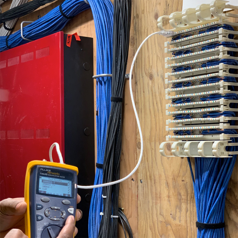
I began the project with visits to several buildings under construction in order to better understand the existing workflows of the network cable professionals, their thoughts about existing CableIQ devices, and opportunities for making their work easier.
Technicians needed more than a device to run live tests—they also needed easier ways to define their test parameters and manage test results for multiple projects, and this is where the CableIQ's capabilities and hardware were most limited.
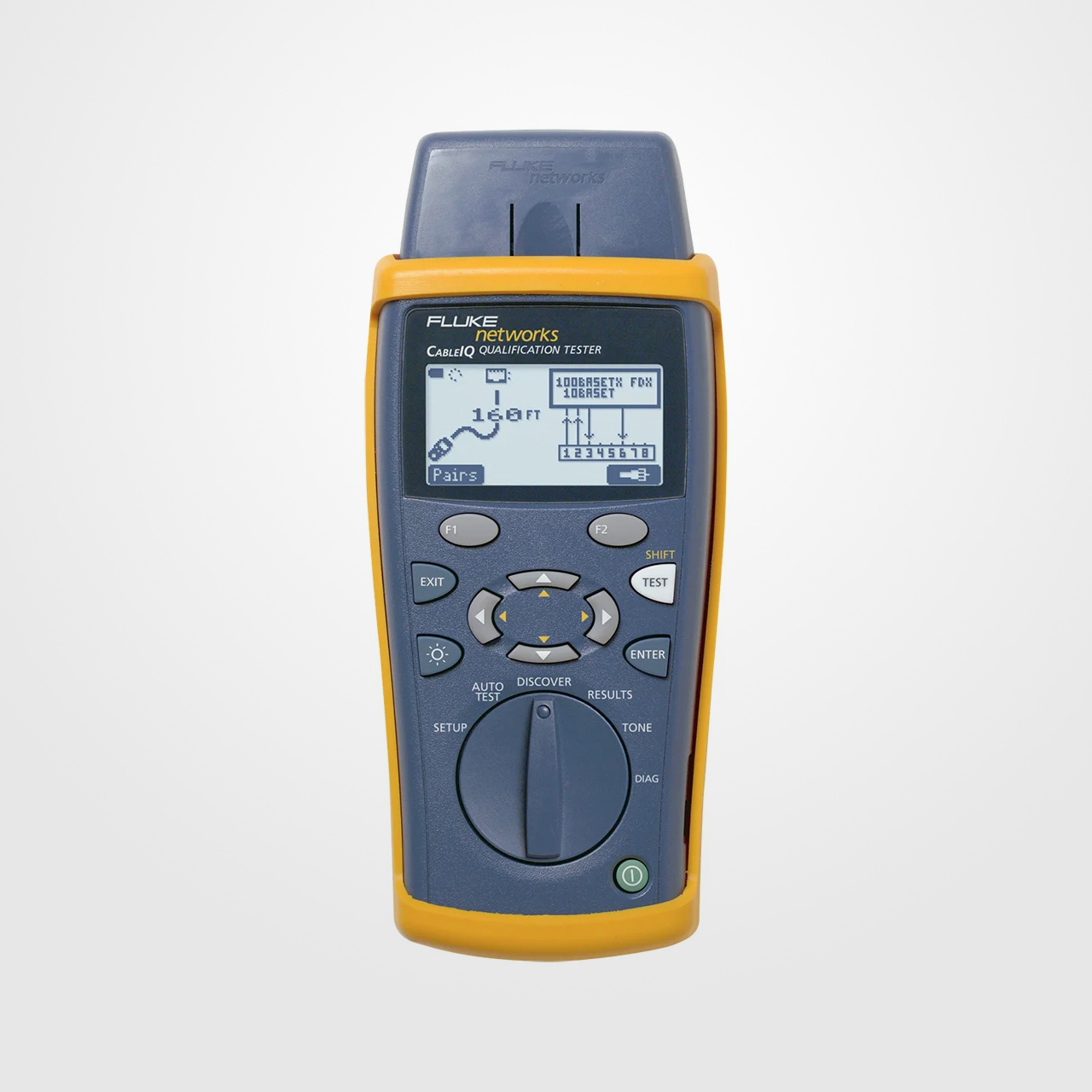
Existing CableIQ and CableID Devices
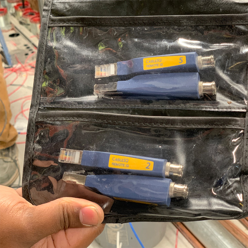
A typical wiring test has two technicians—the device operator is located at the wiring panel, and the other technician has RemoteID devices at endpoints somewhere else in the building.
They are communicating via walkie-talkie.
Testing devices are set up beforehand with parameters that determine if a test will pass or fail.
With the device set up, a test can begin once the device is connected to a node at the wiring panel and a remoteID is connected to an endpoint.
When a test is run, the device identifies the type of device connected at the endpoint and the length of the cable, along with a wiremap diagram showing which wires are connected, open, short, or crossed over.
Test details will also show the network speed supported by cables, and in certification scenarios, test results are only saved if they pass.
Otherwise, the technicians run diagnostic tests, troubleshoot the issues, and if necessary, replace wiring before re-running the test.
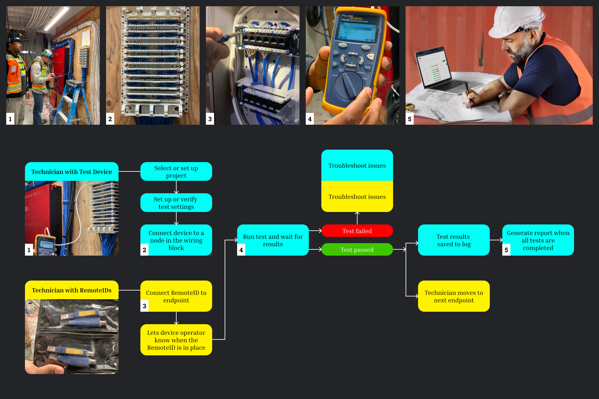
Workflow for Wiring Certification
After conducting the site visits, I completed an audit of the existing CableIQ information architecture to get a better understanding of the features we'd need to support as well as opportunities to streamline user flows.
Cable technicians had previously expressed confusion about the differences between the Discover and Auto Test workflows on the CableIQ, and this became apparent as I documented its information architecture.
Test setup and text input were also areas that were extremely difficult with the existing CableIQ hardware.
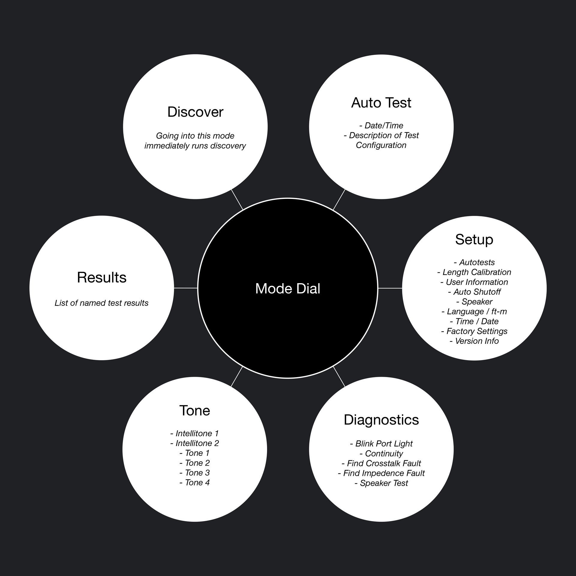
CableIQ High-Level Information Architecture
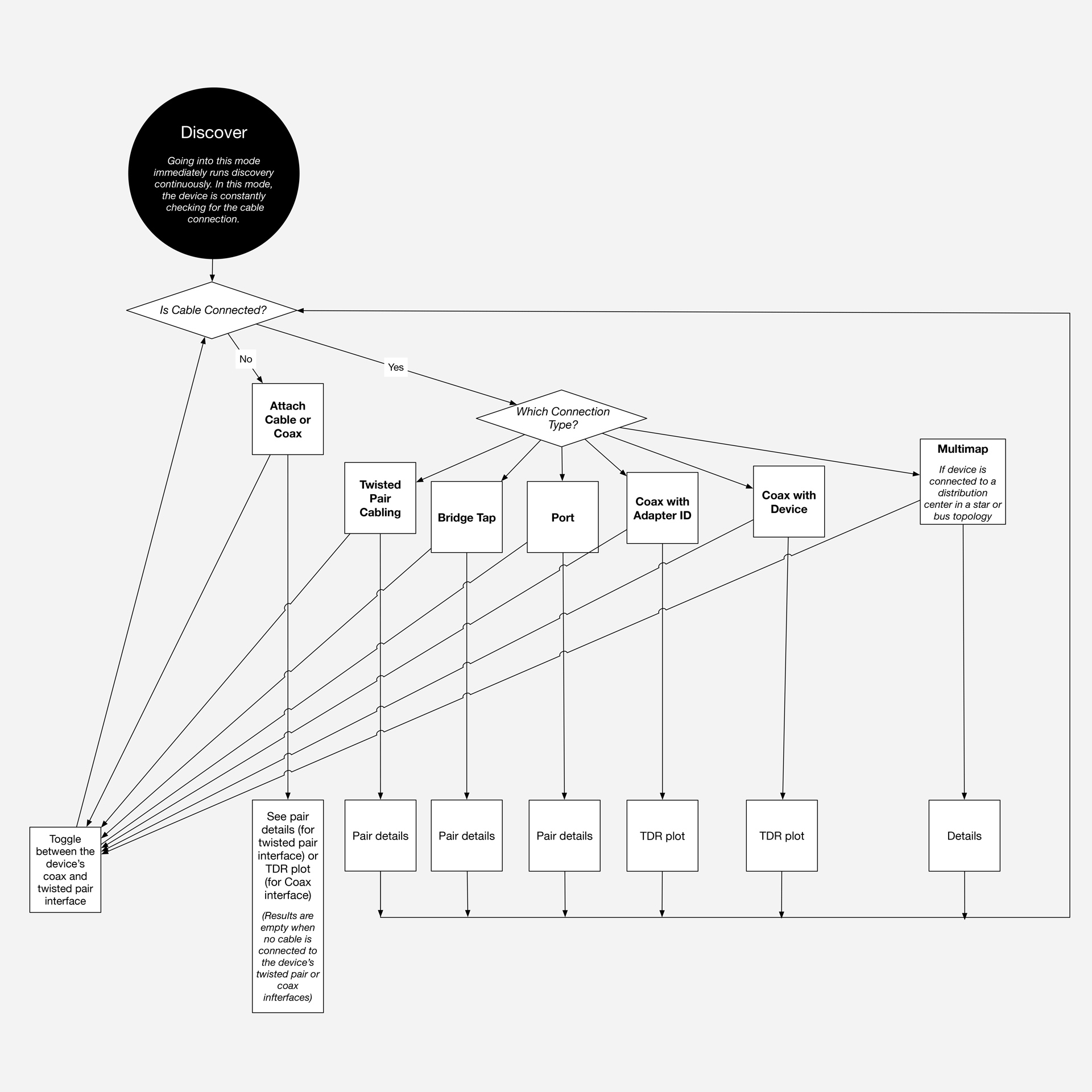
CableIQ Discover Information Architecture
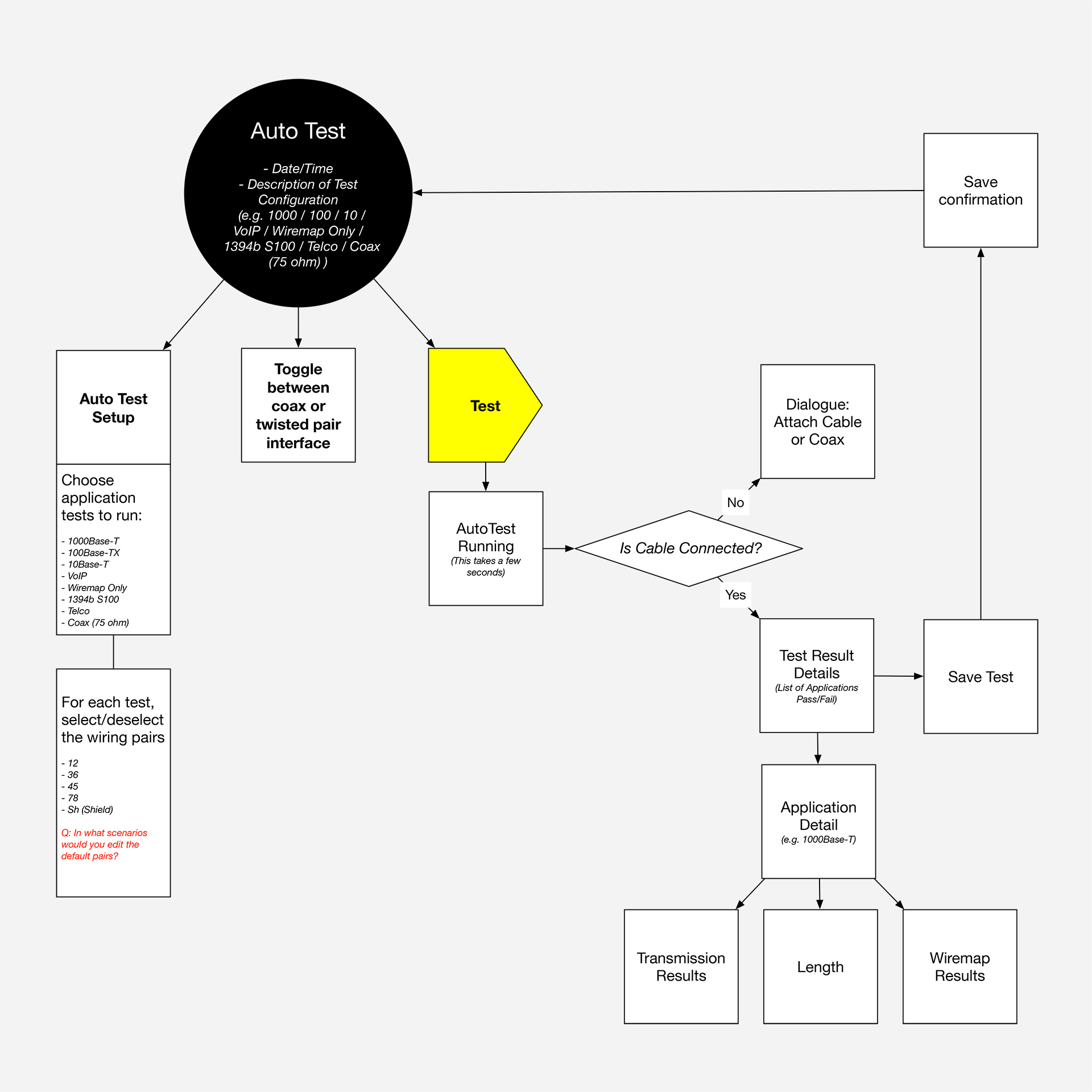
CableIQ Auto Test Information Architecture
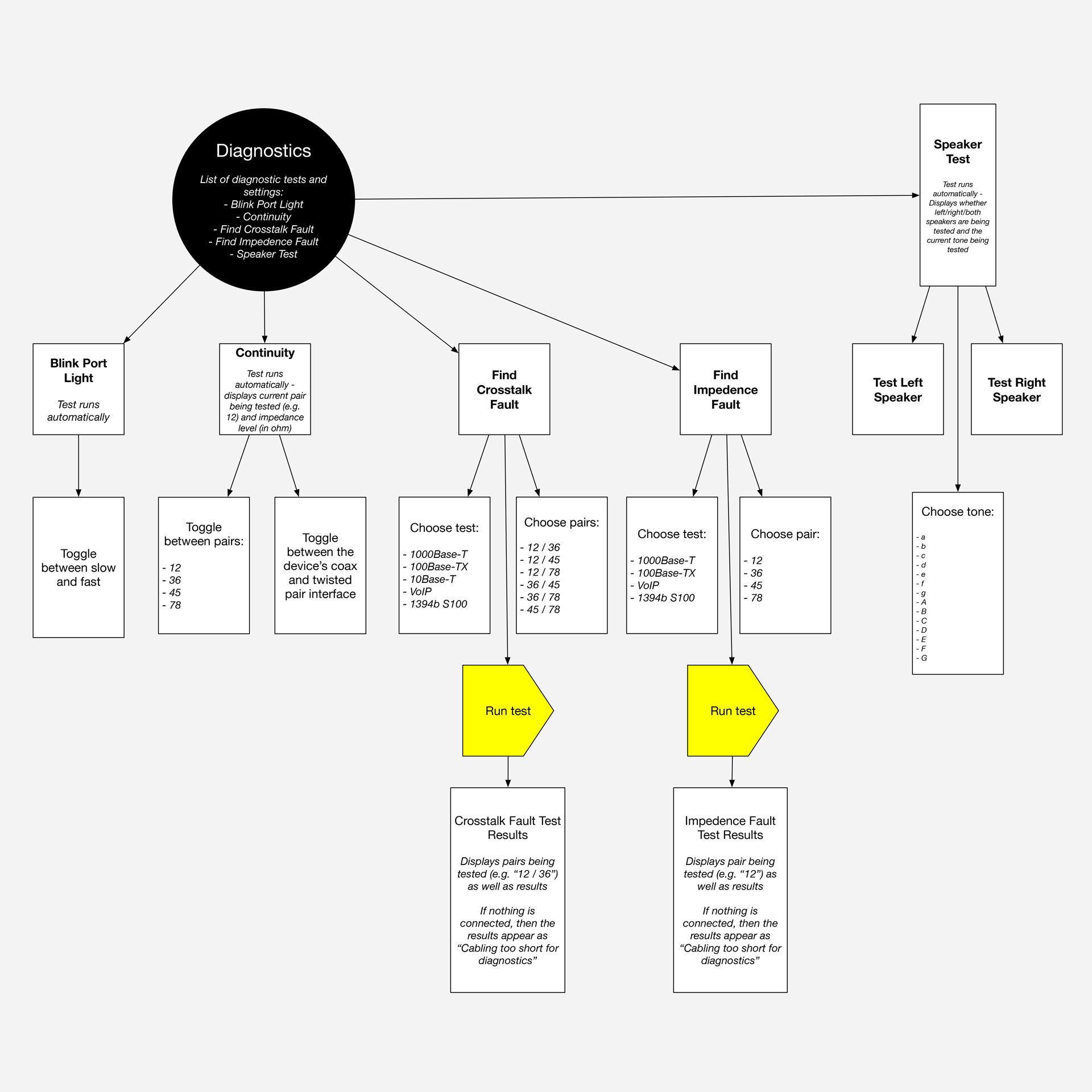
CableIQ Diagnostics Information Architecture
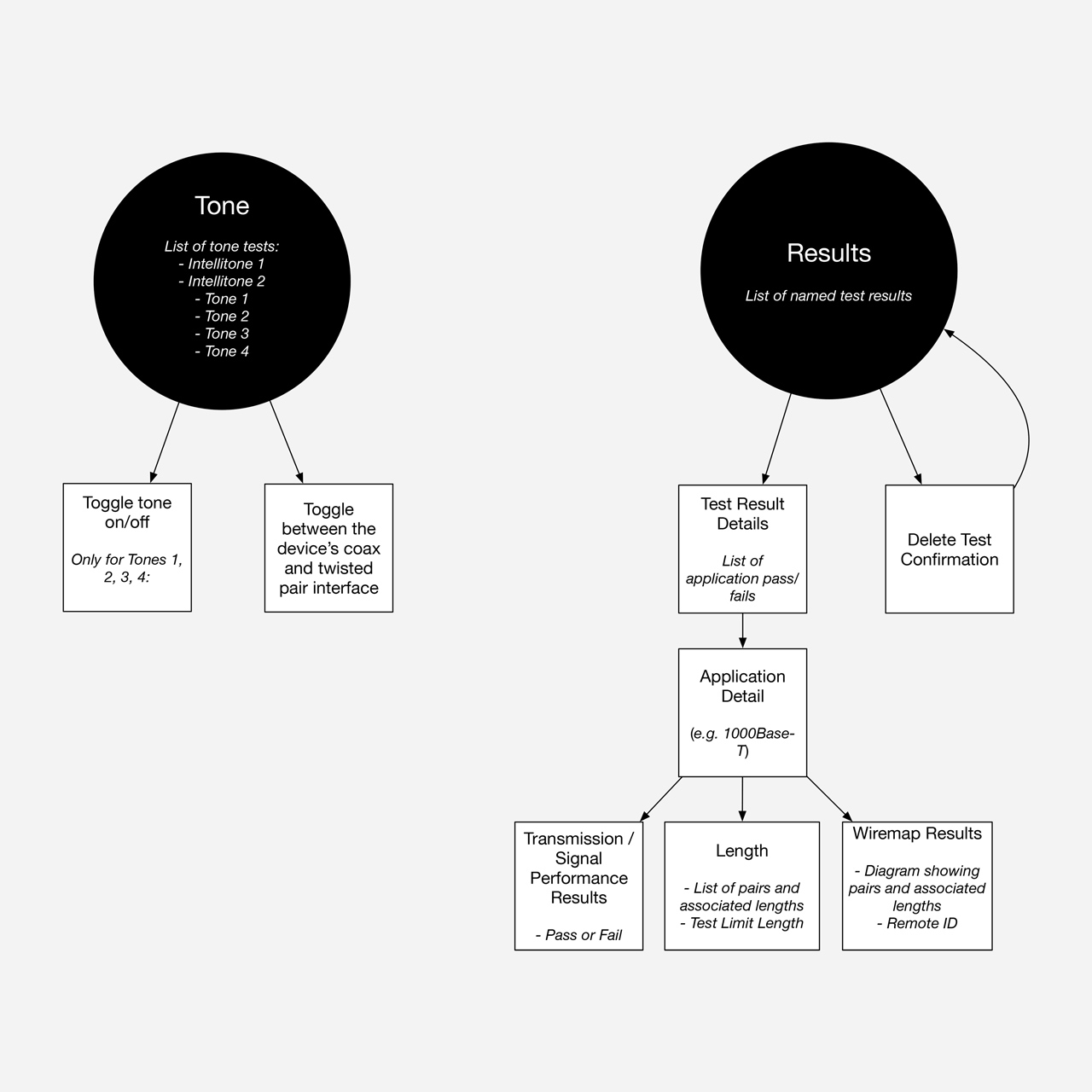
CableIQ Tone and Results Information Architecture
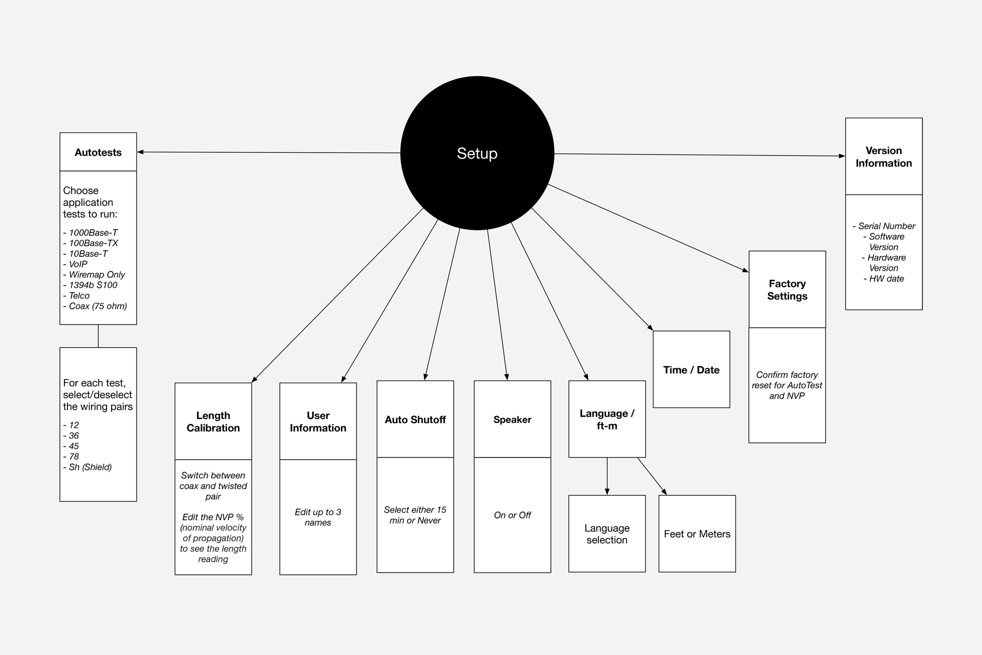
CableIQ Setup Information Architecture
Initial Wireframe Sketches
Although other hardware interfaces were considered, the gaps between the scope of features technicians needed most and what existing devices could easily do ultimately drove our decision to design an exclusively touchscreen interface for the new LinkIQ device.
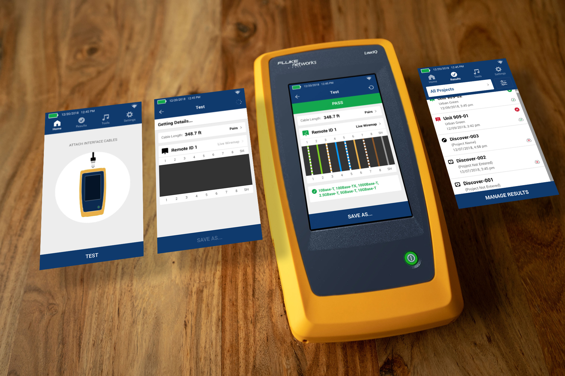
Whenever the device is powered on and interface cables are attached, LinkIQ can start running tests without manually switching the hardware controls to testing mode.
Setting up test parameters are also simplified with onscreen controls, and technicians can easily name and save test results within different project folders.
LinkIQ devices could be further future-proofed with new screen-based features.
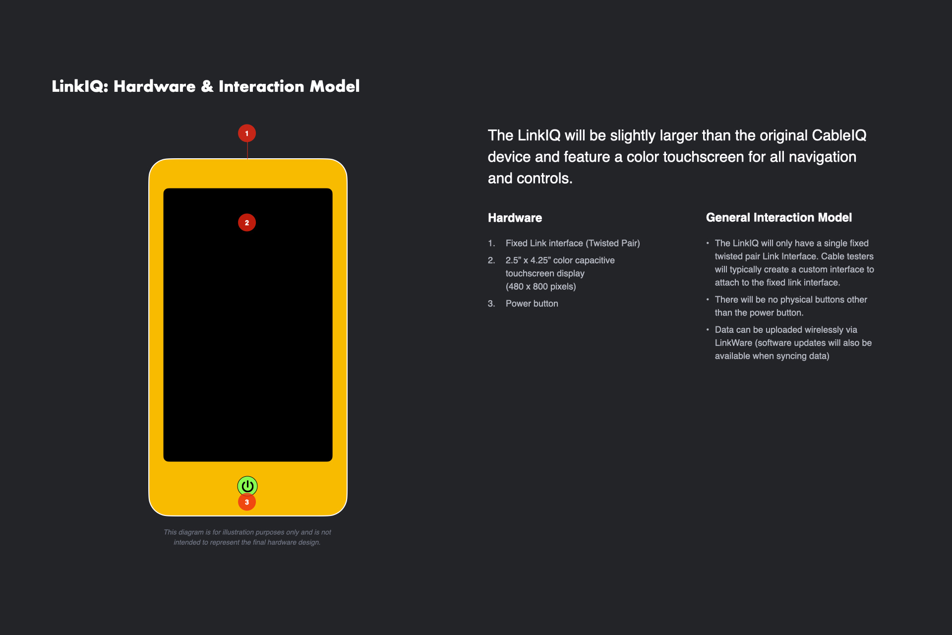
LinkIQ Hardware Diagram
For the initial sketches, I suggested tabs roughly corresponding to the rotary dial of the existing CableIQ device.
Auto Test and Discover could be combined into a single Discover tab, while Toner and Diagnostics were often used for similar purposes.
Transfer would be a new tab that would support the additional capabilities of this device to wirelessly transfer test results to a cloud storage account.
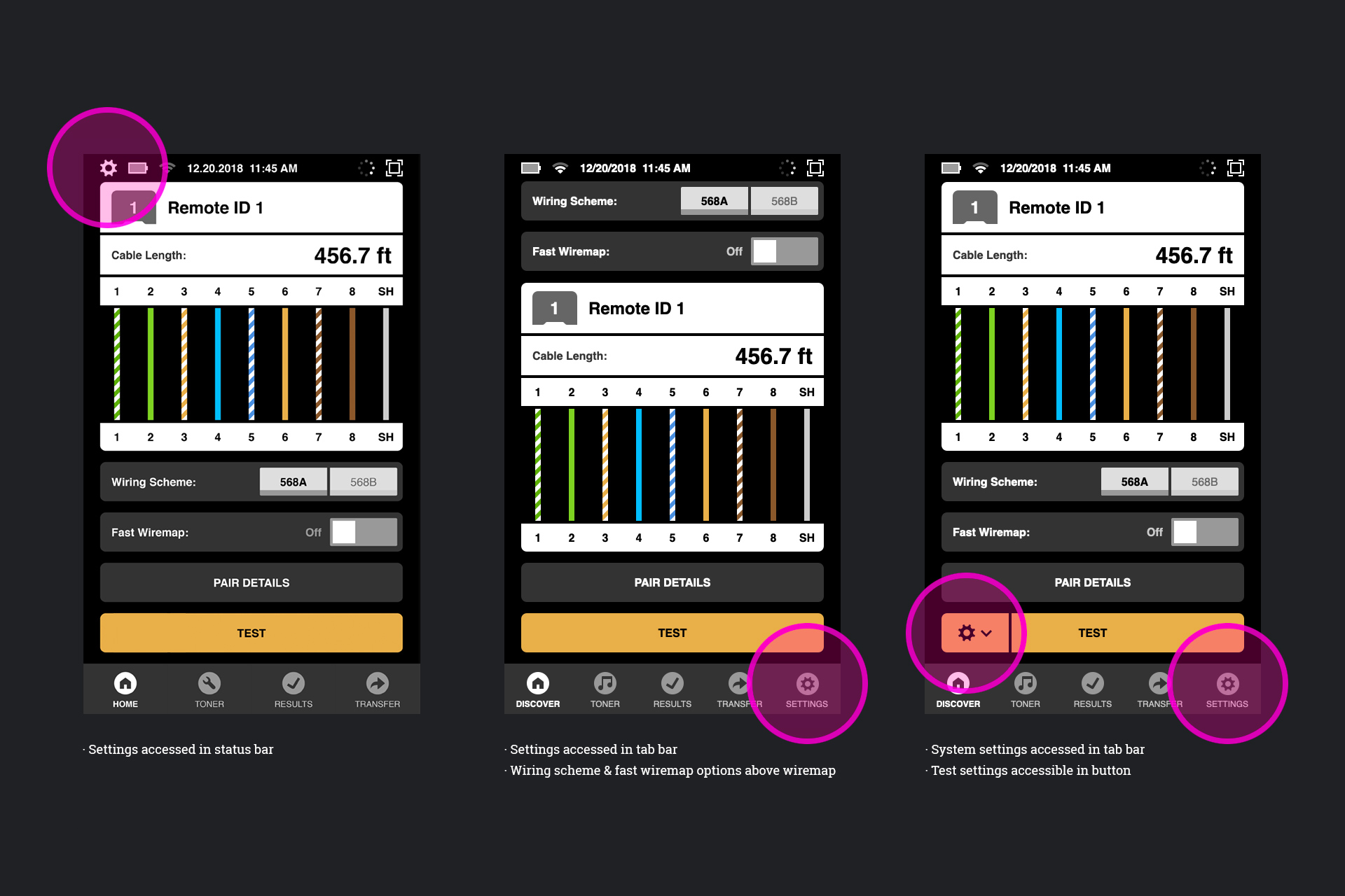
Exploring placement of test settings
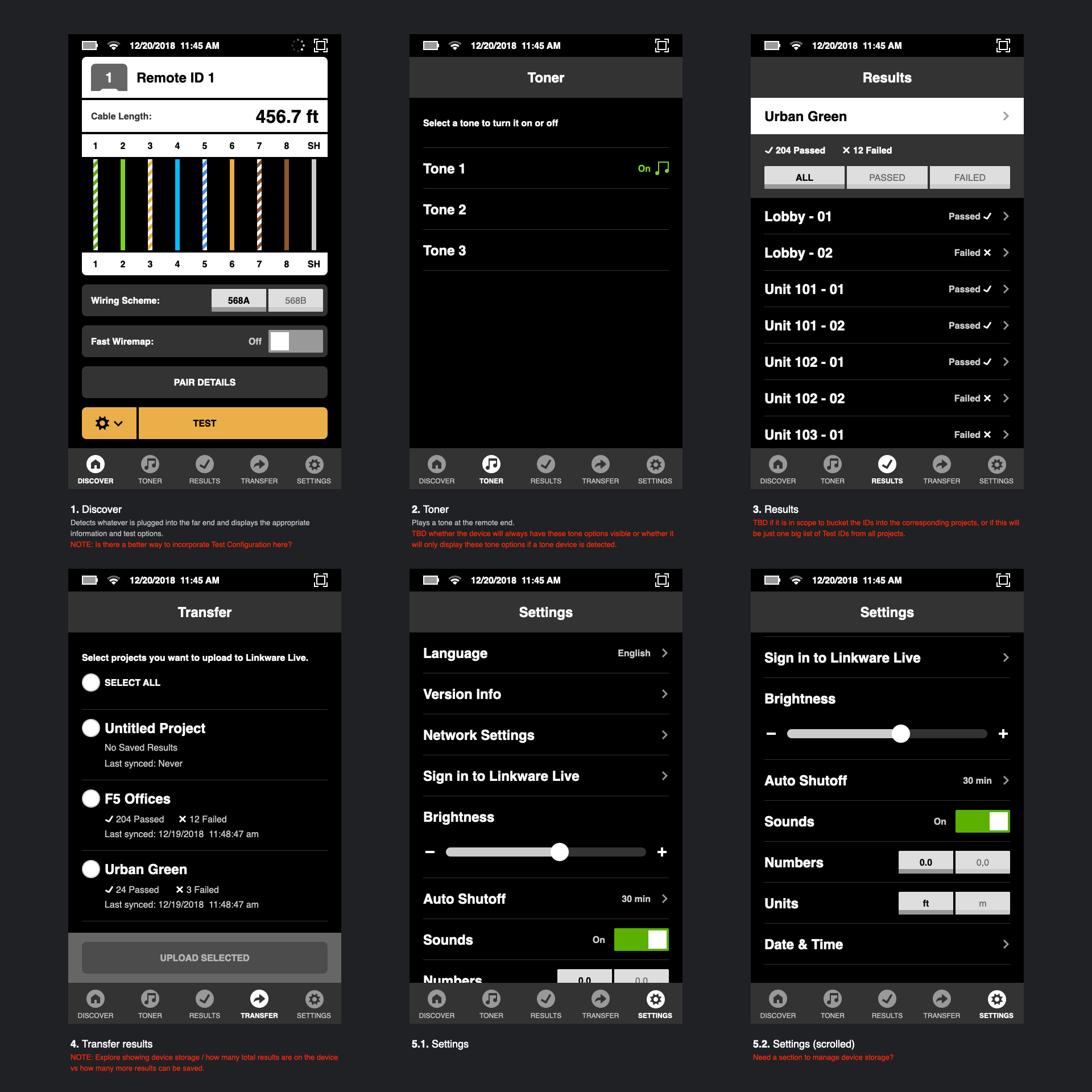
Top Level UI Sections
Next, I worked closely with Fluke Networks and talked with technicians to understand the information and features needed to set up and run tests.
In designing the live wiremap test results, I was exploring ways to create a consistent structure to display information for a variety of testing outcomes.
Setting up tests involved establishing the networks speeds required to pass a test and which wiring pairs to test for each speed.
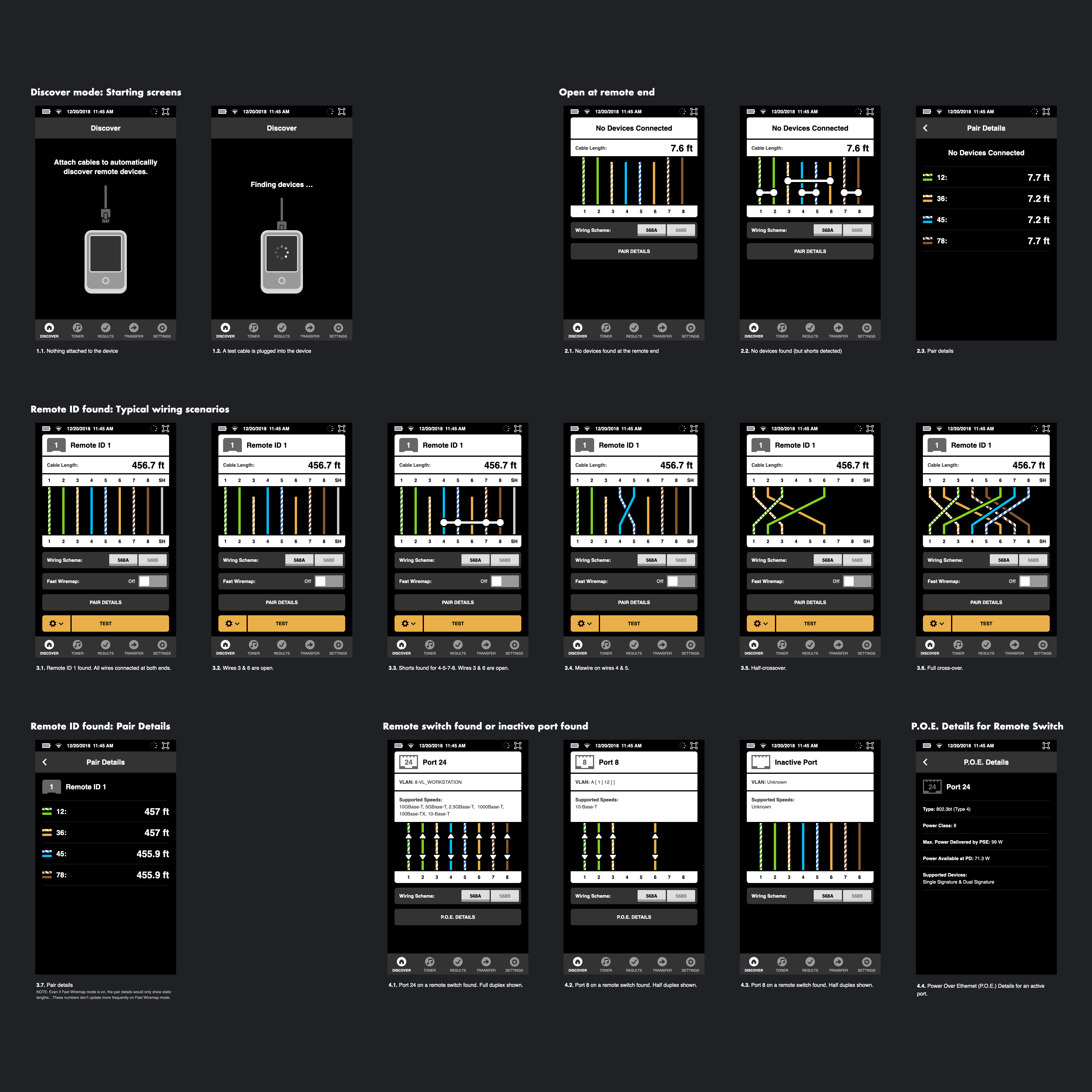
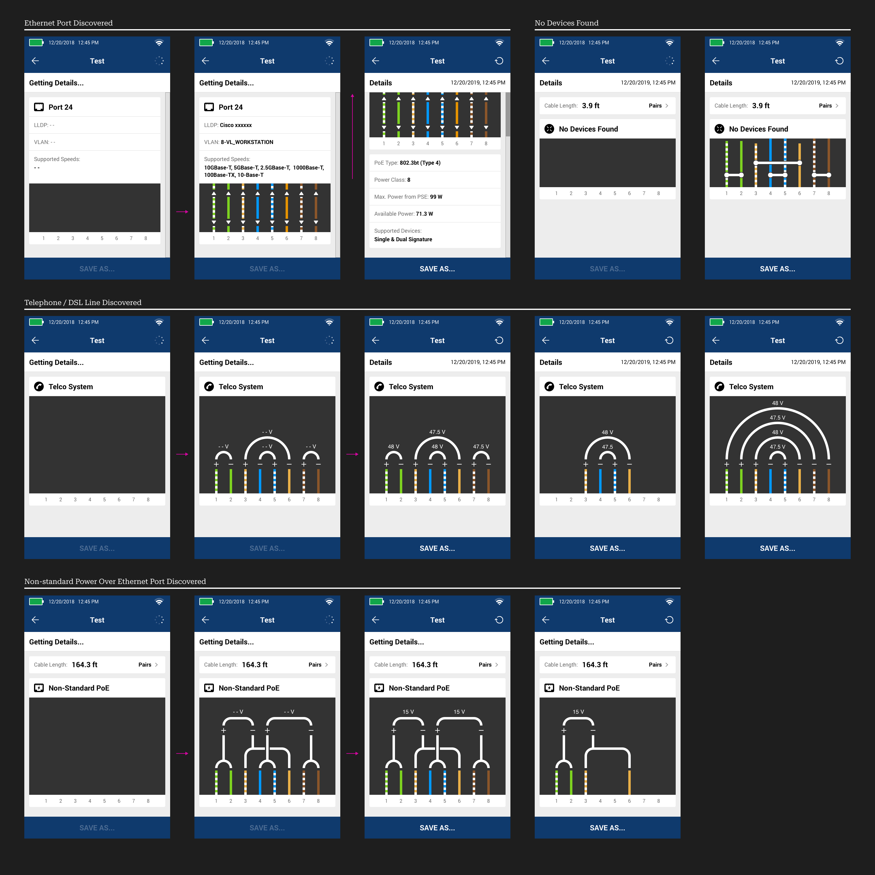
Typical Test Outcomes
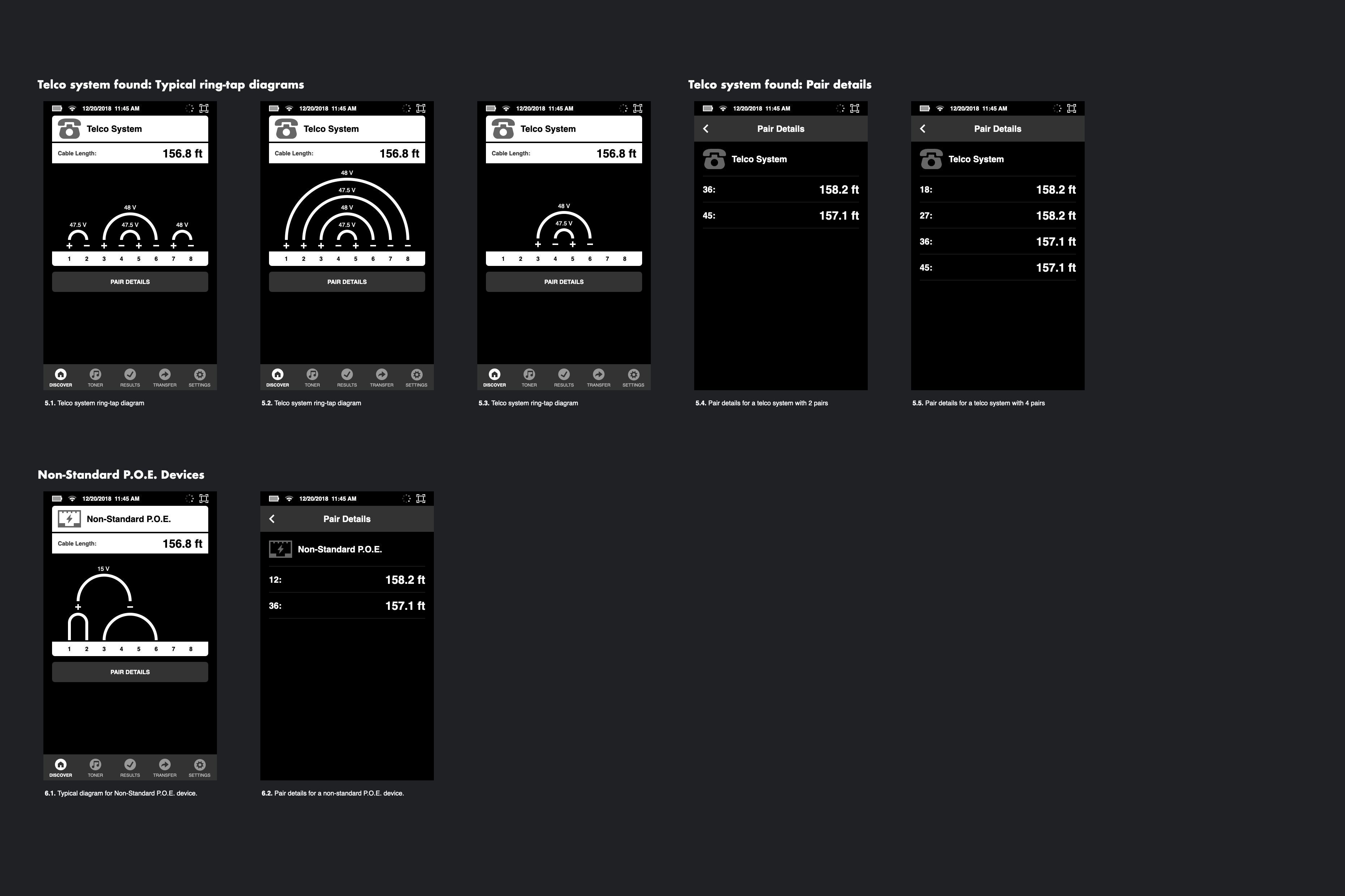
Telco and Non-Standard Power over Ethernet Devices Found
Detailed Test Results
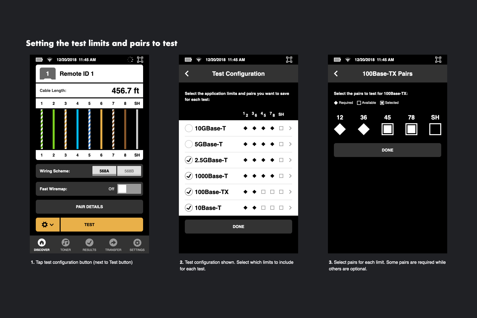
Test Settings
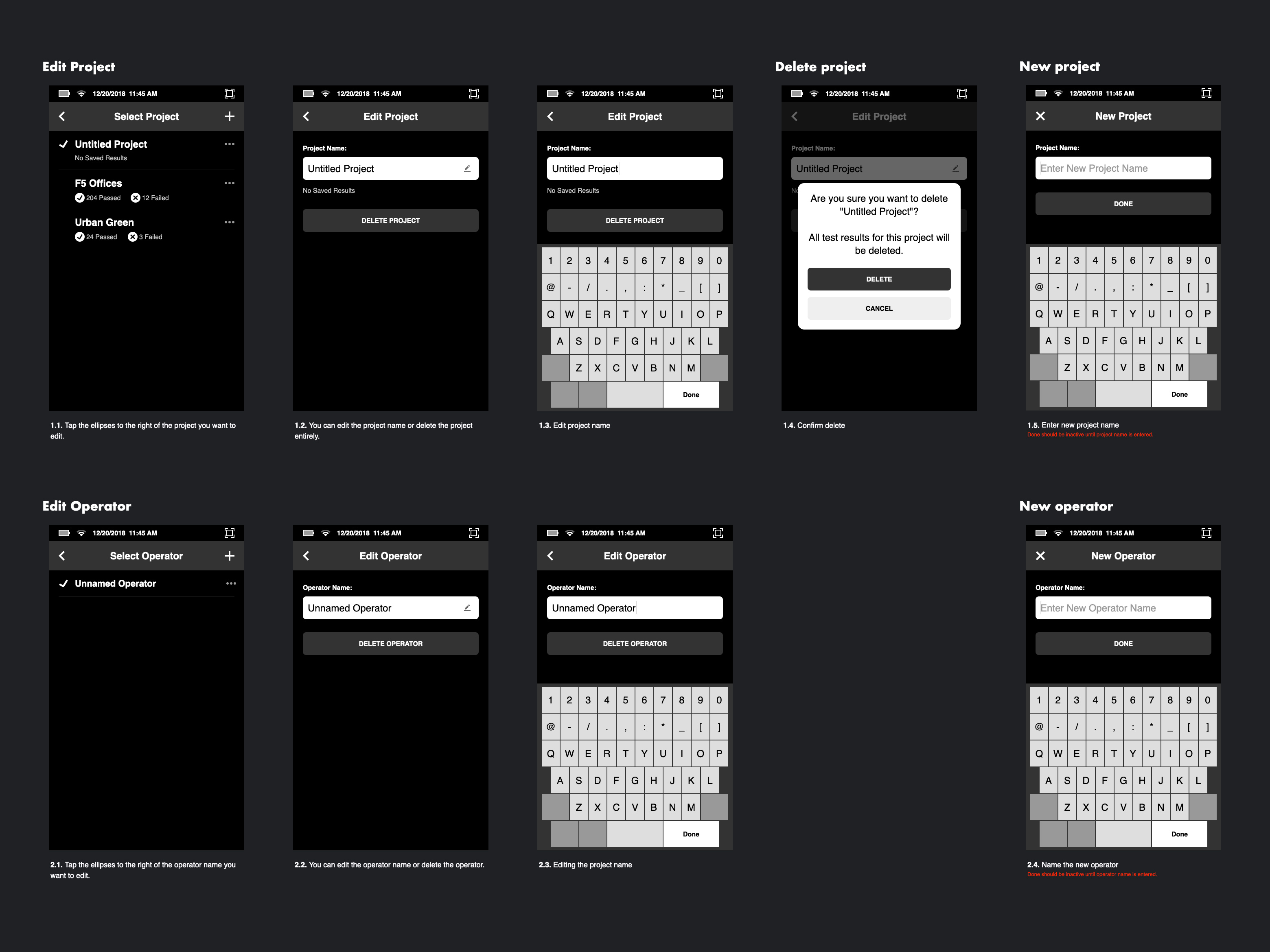
Editing Projects and Operators
Visual Design
Working within Fluke Network's brand guidelines, I created rough visual concepts with the goal of soliciting feedback on the use of icons, illustrations, and how their overall color palette should be applied.
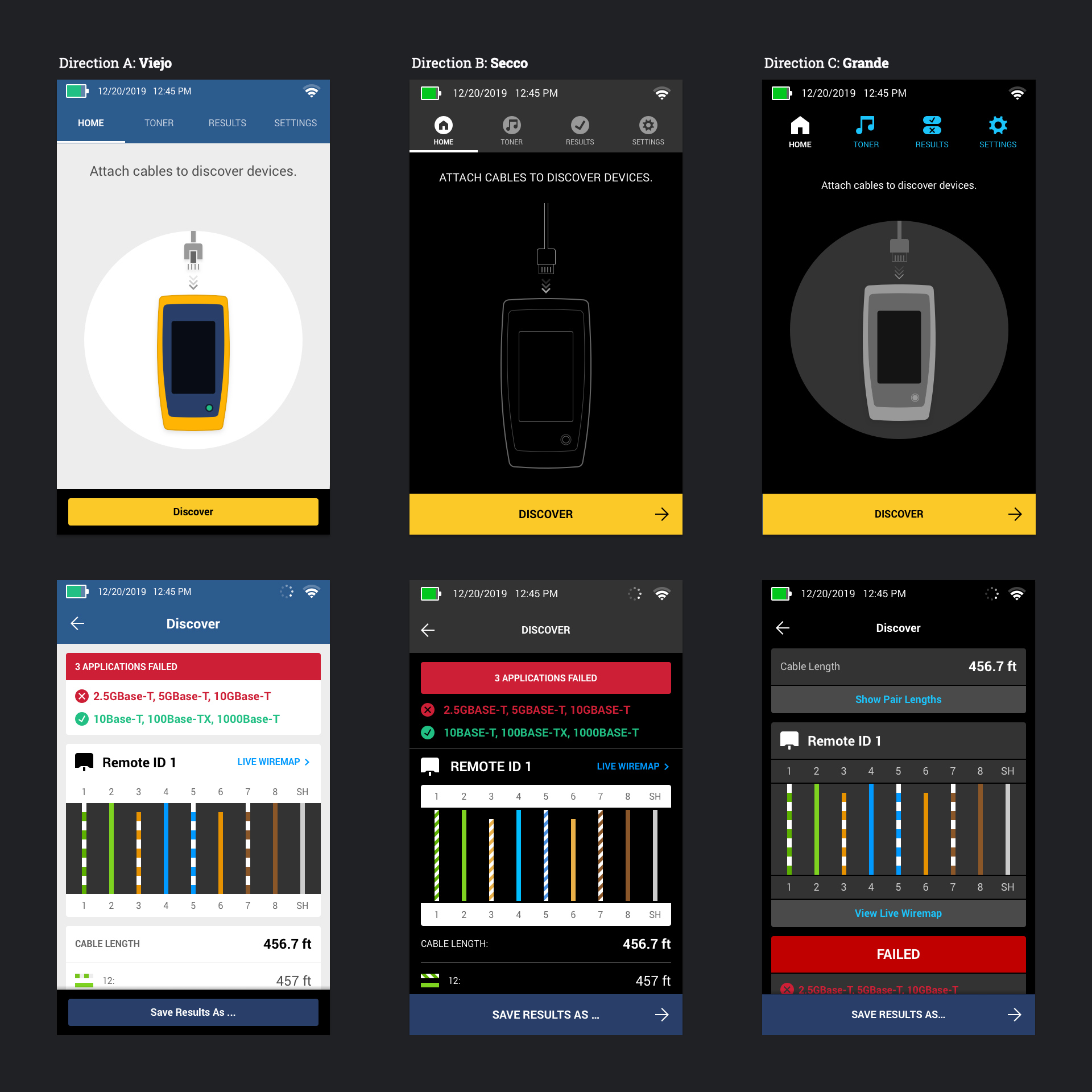
Initial Visual Design Concepts
The team preferred the use of a lighter color palette matching their desktop applications, and I proceeded to refine the flows and design details with this direction.
During detailed design, I found opportunities to streamline user flows and apply more consistent design patterns.
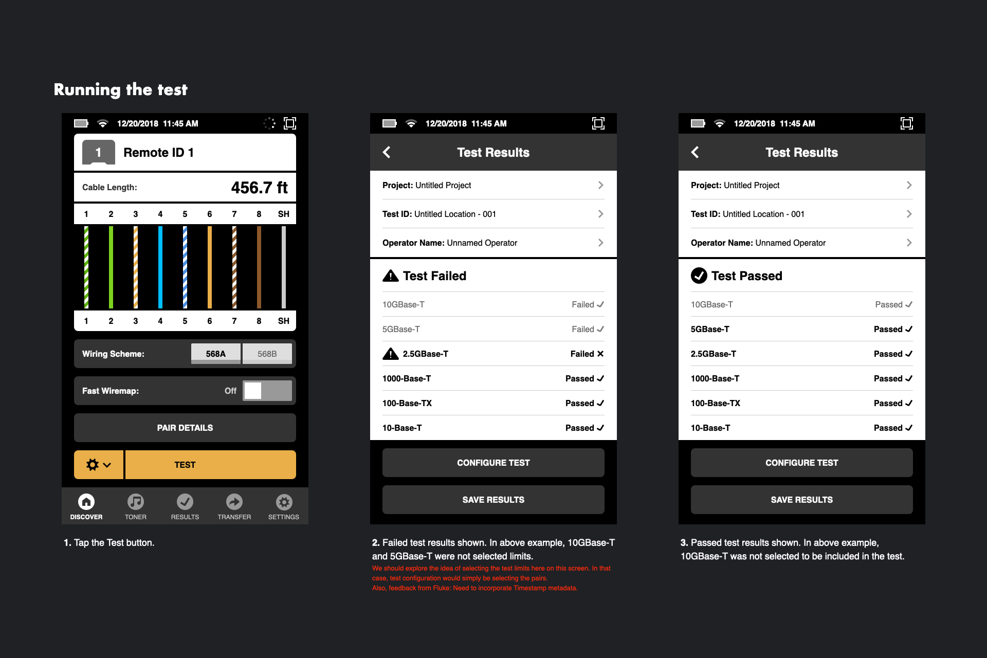
For example, wiring details could appear progressively and without the technician having to manually tap a TEST button.
My final deliverables also included interactive prototypes built in Flinto and a library of UI components built in Sketch.
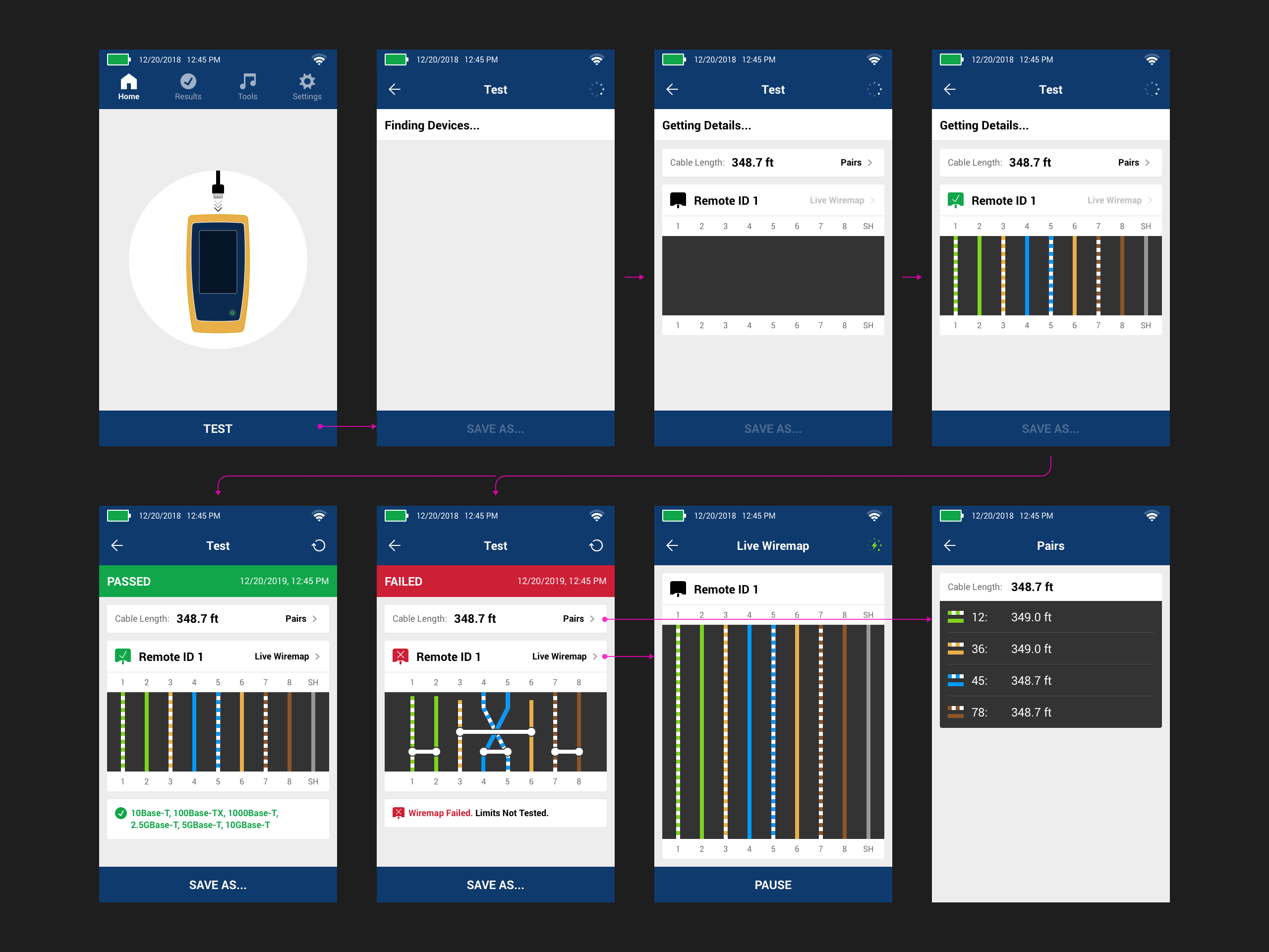
Starting a Wiring Test
Typical Test Results
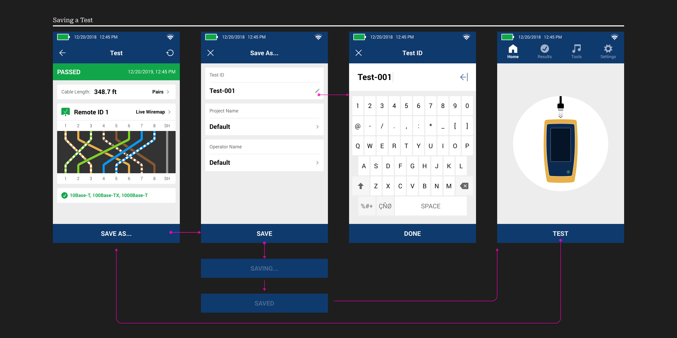
Saving a Test
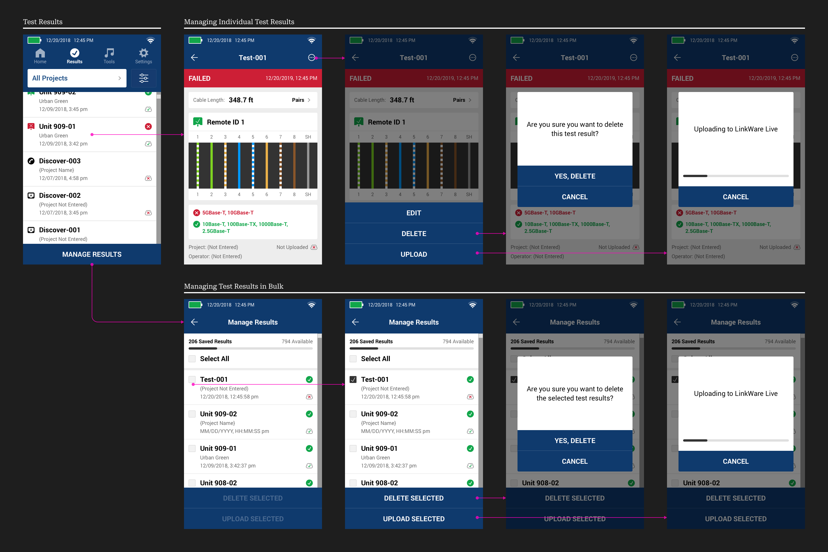
Managing Test Results
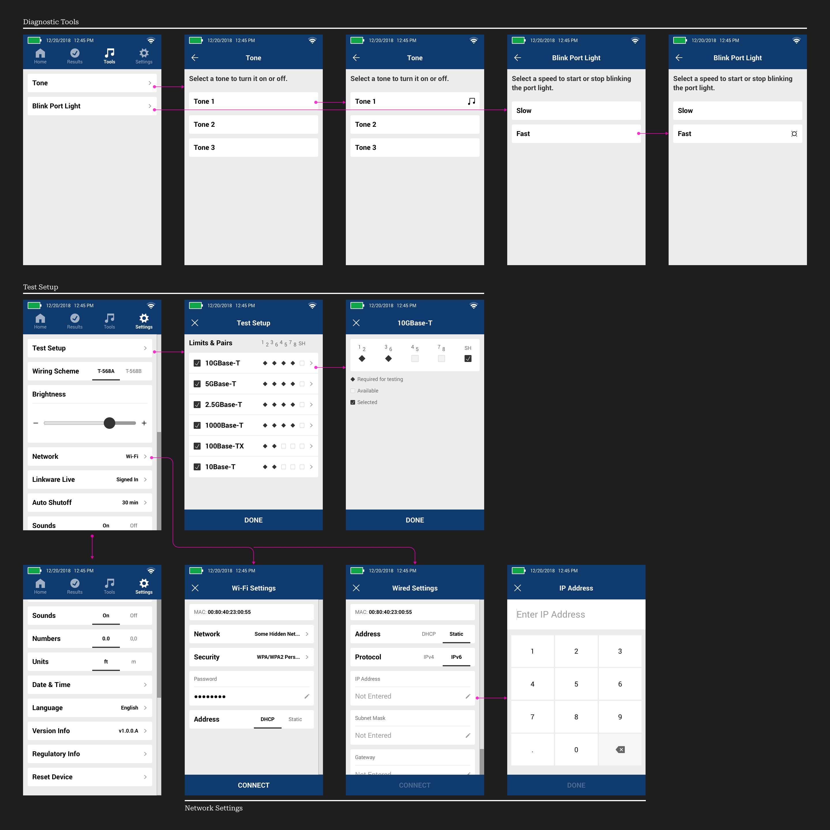
Diagnostic Tools and Settings